Coastal Slope Stabilisation Using 2D and 3D Analysis
This coastal slope stabilisation case study examines a localised residual-soil failure at the top of a near-vertical coastal cliff following an extreme rainfall event.
TSLOPE was used to back-analyse the observed failure in both 2D and 3D, assess the full cliff profile, and model an anchored mesh reinforcement system intended to reduce the risk of further retreat at the cliff edge.
We installed the slope stabilisation works designed with TSLOPE. From a contractor’s perspective, the design was clear, practical to implement, and provided an effective solution for the site conditions.
The ability to model the slope in 3D was particularly useful as this provided a more realistic representation of the failure geometry and helped optimise the anchor spacing to the benefit of the client.
Approximate height of the coastal cliff at the analysed location.
The main rock face was close to vertical.
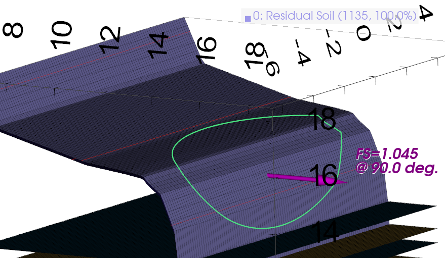
The observed failure was represented using a finite-width 3D surface.
The reinforcement concept was developed for a 25-year design life.
Project Background
The site comprised a coastal cliff formed within alternating sandstone and siltstone layers. A layer of residual soil derived from weathered rock covered the upper edge of the cliff.
Following several days of exceptional rainfall, a localised section of the residual soil failed at the bevelled cliff edge. The observed condition indicated that the soil had become saturated, reducing its available strength.
The principal engineering objective was to help maintain the existing cliff-top edge and reduce the risk of further shallow failures within the residual soil.
Site conditions
- Near-vertical coastal rock cliff
- Residual soil over sandstone and siltstone
- Localised rainfall-triggered failure
- Significant groundwater and runoff during heavy rain
- Ongoing long-term coastal weathering and erosion
Engineering assessment
- UAV survey and photogrammetric point-cloud model
- 2D and 3D back-analysis of the observed failure
- Full-height cliff stability analysis
- Anchored mesh reinforcement modelling
- Comparison of alternative anchor layouts
UAV Geometry and TSLOPE Model Setup
A UAV survey was used to capture the cliff face and surrounding ground surface. The survey data was processed into a detailed three-dimensional point cloud and used to develop the slope geometry.
A representative cross-section was extracted from the point cloud for the 2D analysis. The section was simplified where necessary to remove rock overhangs that would otherwise create unsupported hanging slices.
The cross-section was then imported into TSLOPE. The same project geometry was used to assess the slope as a 2D section, an extruded 3D model, and a model incorporating the surveyed three-dimensional geometry.
Back-Analysis of the Observed Failure
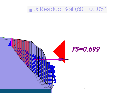
The observed residual-soil failure was analysed using Spencer’s Method in both 2D and 3D.
To represent the saturated conditions associated with the extreme rainfall event, the phreatic surface was positioned 0.1 metres below the ground surface.
The critical circular failure surface was first identified in 2D. This surface was then used to create an approximately eight-metre-wide 3D ellipsoid matching the observed width of the failed area.
| Analysis | Failure representation | Factor of Safety |
|---|---|---|
| 2D Spencer | Critical circular surface through the residual soil | 0.70 |
| 3D Spencer | Approximately 8 m wide ellipsoid matching the observed failure | 1.05 |
Why the 2D and 3D Results Differed
A conventional 2D analysis assumes that the same failure mechanism continues indefinitely perpendicular to the cross-section.
The actual failure was localised and had a finite width. The 3D analysis represented the geometry of the failed mass and the additional resistance developed around its sides.
The 3D factor of safety of 1.05 was close to unity, as expected when back-analysing a slope failure that had already occurred. The corresponding 2D result of 0.70 was substantially lower.
The project showed that a localised failure could not be fully represented as an infinitely wide 2D mechanism.
Modelling the Reinforcement System
The proposed stabilisation system used high-strength mesh secured by rows of grouted steel anchors.
Three principal anchor rows were modelled along the cliff edge, with an additional short row within the previously failed area. The anchors were designed to extend through the residual soil and develop their bond resistance within the underlying rock.
Initial arrangement
- Three principal rows of anchors
- Approximately 2.0 m horizontal spacing
- Six-metre anchor lengths
- Maximum modelled anchor force of 50 kN
- Steeper upper anchors to reach the underlying rock
Revised arrangement
- Horizontal spacing increased to 2.5 m
- Top-row anchor length retained at 6 m
- Middle-row anchor length reduced to 5 m
- Lower-row anchor length reduced to 4 m
- Middle-row inclination increased to improve rock embedment
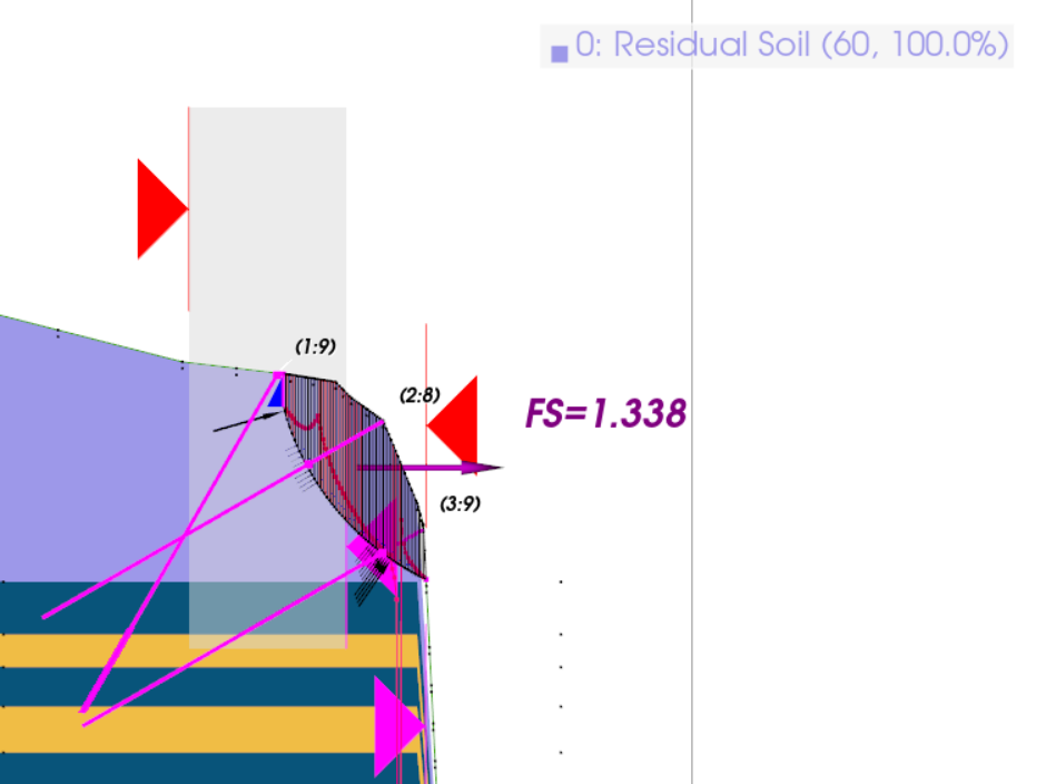
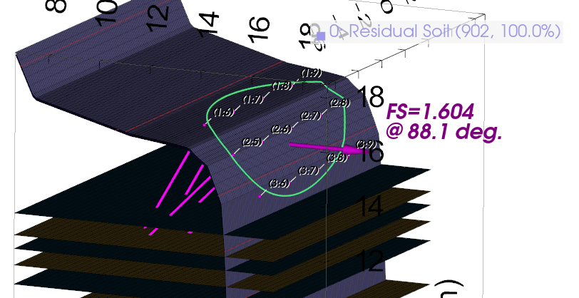
The images above show two different stages of the reinforcement design. The 2D image shows the initial arrangement, while the 3D image shows the revised layout.
Reinforcement Results
Both reinforcement arrangements increased the calculated stability of the saturated residual-soil slope.
The initial arrangement produced the greatest calculated increase. A second analysis then assessed a more efficient layout with wider spacing and shorter anchors.
| Slope case | 2D Factor of Safety | 3D Factor of Safety |
|---|---|---|
| Saturated residual soil before reinforcement | 0.70 | 1.05 |
| Initial reinforced arrangement | 1.34 | 2.46 |
| Revised reinforced arrangement | 1.24 | 1.60 |
Full-Height Cliff Analysis
The assessment also considered a potential failure involving the full height of the cliff, including the alternating sandstone and siltstone layers beneath the residual soil.
The unreinforced full-height analyses produced factors of safety of 1.50 in 2D and 1.67 in 3D. These results indicated that the immediate concern was the shallow residual-soil failure at the cliff edge rather than a deep-seated failure through the full rock profile.
| Full-height slope case | 2D Factor of Safety | 3D Factor of Safety |
|---|---|---|
| Full-height cliff without reinforcement | 1.50 | 1.67 |
| Full-height cliff with initial reinforcement | 1.54 | 1.72 |
| Full-height cliff with revised reinforcement | 1.50 | 1.65 |
Completed Coastal Slope Stabilisation
The drone footage shows the coastal slope after installation of the anchored mesh reinforcement system.
How TSLOPE Supported the Assessment
2D and 3D in one package
The critical 2D failure surface could be developed and then used as the basis for a corresponding 3D failure surface without transferring the project between separate slope stability programs.
Finite-width failure modelling
The three-dimensional failure surface could be sized to match the approximate width of the failure observed in the field.
Survey-based geometry
Geometry developed from UAV point-cloud data could be used to represent the steep and irregular coastal slope.
Reinforcement assessment
Anchor spacing, length, inclination, bond resistance and force capacity could be assessed in both 2D and 3D.
Engineering Takeaway
The assessment found that the shallow residual soil at the cliff edge was vulnerable to failure when saturated during extreme rainfall.
TSLOPE’s 3D back-analysis produced a factor of safety close to unity for the observed finite-width failure. The equivalent 2D analysis produced a substantially lower result because it treated the failure as an infinitely wide mechanism.
The proposed anchored mesh system substantially increased the calculated stability of the residual-soil slope. Alternative anchor layouts could then be tested to assess whether wider spacing and shorter anchors could still provide an acceptable result.
Analyse Reinforced Slopes in 2D and 3D with TSLOPE
TSLOPE supports 2D and 3D limit equilibrium analysis for natural slopes, coastal cliffs, reinforced slopes, dams, embankments and other geotechnical models.
- Complete 2D and 3D analyses in one program
- Import real-world terrain and survey geometry
- Model finite-width 3D failure surfaces
- Represent groundwater using phreatic surfaces
- Assess anchors and other reinforcement
- Compare alternative stabilisation layouts