Model Review and Analysis Checks in TSLOPE
Review failure mechanisms, stress distribution, tension, weak layers, and differences between 2D and 3D slope stability results.
Read the technical note →In 3D slope stability analysis, sliding direction is not just a visual setting. It affects the calculated factor of safety and the way stabilising measures such as anchors should be positioned.
In a 2D section, the direction of movement is usually implied by the section itself. In 3D, the slope can fail in different directions depending on the relationship between the ground surface, basal geometry, weak layers, groundwater, loading, and support.
This note explains why sliding direction affects the calculated factor of safety, why manually assuming a direction can miss the critical mechanism, and why movement direction matters when reviewing anchor orientation and other stabilising measures.
Sliding direction influences how the software resolves the driving and resisting forces acting on the potential failure mass.
A change in direction can change the calculated factor of safety, even when the same general slope geometry and basal surface are being analysed.
This matters because engineers are not only asking whether a slope is stable. They are also trying to understand the likely movement direction, the controlling failure mechanism, and what design response makes sense.
In short: the same 3D slope can produce different factors of safety when analysed in different possible movement directions.
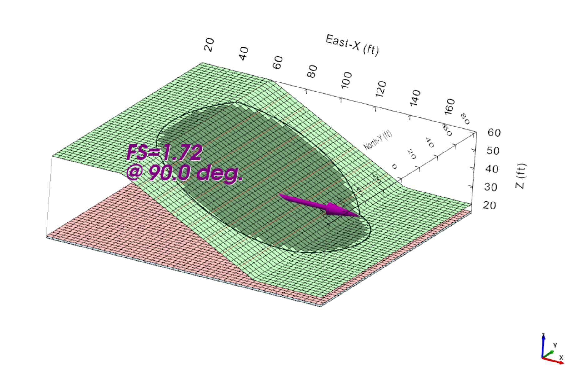
In a 2D slope stability section, the direction of movement is normally defined by the orientation of the section. The analysis considers movement within that plane.
In a 3D model, the potential failure mass is not restricted to a single section. It may move across the ground surface at an oblique angle, follow a curved geological feature, or respond to irregular topography and loading.
The apparent downslope direction shown by the surface terrain is therefore not always the direction associated with the lowest factor of safety.
If the sliding direction is manually assumed, the model may not capture the most critical failure mechanism.
A direction that looks reasonable on screen may not be the direction that produces the lowest factor of safety.
This becomes more important as the 3D geometry becomes less uniform. Small changes in movement direction can alter which parts of the basal surface, weak layer, or slope geometry control the result.
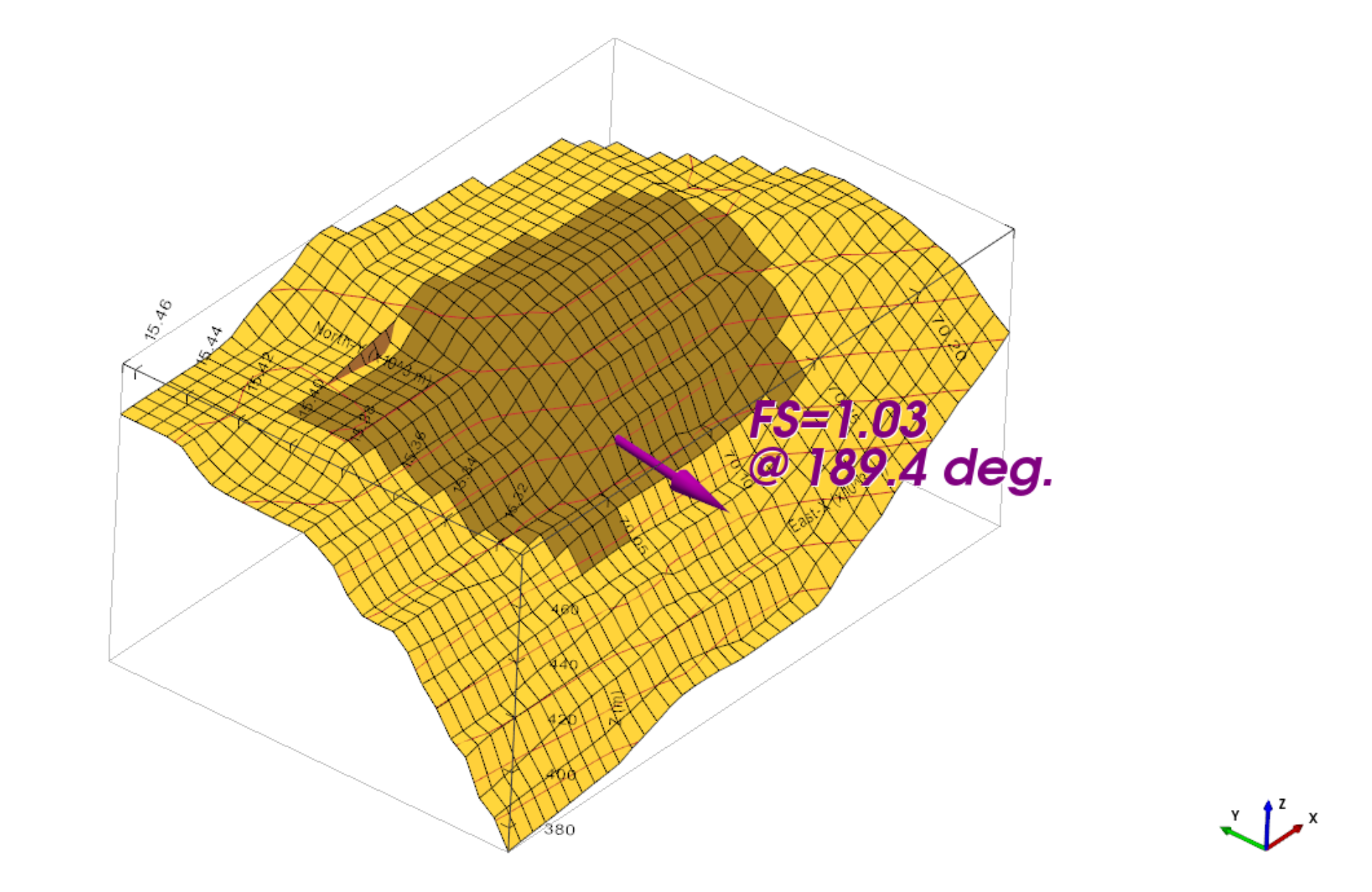
TSLOPE searches for the sliding direction associated with the lowest factor of safety.
Rather than requiring the engineer to manually select the movement direction first, TSLOPE identifies the critical direction as part of the 3D analysis process.
The resulting direction feeds into the calculation of the failure mechanism and gives engineers a clearer basis for reviewing the result.
TSLOPE identifies the direction associated with the lowest factor of safety rather than relying only on a manually assumed movement direction.
The critical direction is influenced by the three-dimensional relationship between the ground surface and the basal surface.
A failure mass may move toward the visually steepest part of the slope, but it may also be redirected by geological structure, local changes in geometry, weak interfaces, or a lower-resistance path through the model.
This is one reason why 3D analysis can provide a different interpretation from a selected 2D section. The 3D model can represent movement that does not align neatly with the section chosen for the 2D analysis.
Weak layers can influence both the shape of the failure surface and the direction in which the failure mass is most likely to move.
Where the weak layer changes elevation, orientation, or thickness across the site, the critical sliding direction may be controlled by the geometry of that layer rather than the visible ground surface.
The same applies to geological structures such as bedding, faults, seams, or interfaces. The lowest-resistance movement direction may follow the structure at an oblique angle to the general slope face.
Anchor direction is not simply a drafting choice. Anchors need to provide resistance against the likely movement of the sliding mass.
If the model assumes the wrong sliding direction, the support layout may not be aligned with the critical failure mechanism.
By identifying the direction linked to the lowest factor of safety, TSLOPE helps engineers review whether anchors and other stabilising measures act in an appropriate direction relative to the modelled failure mass.
Consider a reinforced slope where two possible sliding directions appear reasonable from the surface geometry.
One direction may follow the general fall of the slope, while another may be influenced by a weak layer, a local change in geometry, or the orientation of the basal surface.
A 3D analysis that checks the critical sliding direction can show which direction produces the lower factor of safety.
This gives the engineer a stronger basis for reviewing the failure surface, interpreting the result, and assessing anchor orientation.
Identifying the lowest factor of safety direction provides valuable information, but the calculated direction still needs engineering review.
The engineer should compare it with the site geology, topography, groundwater, material strengths, loading conditions, construction history, and any observed signs of movement.
A mathematically critical direction may reveal a plausible mechanism, but it should not be accepted without considering whether that mechanism is realistic for the site.
The software identifies the critical calculated direction. The engineer determines whether that result represents a credible site failure mechanism.
Sliding direction is a core part of 3D slope stability analysis. It affects the factor of safety, the shape of the failure mechanism, and the design interpretation that follows.
TSLOPE identifies the direction associated with the lowest factor of safety, helping engineers review the most critical calculated mechanism rather than relying on a manually assumed movement direction.
This provides a clearer basis for interpreting complex 3D slopes and reviewing whether anchors and other stabilising measures are acting in the right direction.
TSLOPE brings 2D and 3D limit equilibrium slope stability analysis into one licence and identifies the sliding direction associated with the lowest factor of safety.